Plasma Stability & Repeatability
Addressing plasma stability and repeatability issues in semiconductor manufacturing is essential for enhancing product quality and yield. Plasma stability refers to the ability of the plasma to maintain consistent characteristics over time. Instability can manifest as fluctuations in ion density, electron temperature, or energy distribution, leading to variations in the manufacturing process. On the other hand, repeatability refers to the ability to achieve consistent results across multiple manufacturing runs. Lack of repeatability can lead to defects, reduced yield, and increased costs.
Impact on Semiconductor Manufacturing
The stability and repeatability of plasma processes have significant implications, including:
Quality Control
Stable plasma conditions ensure consistent material properties, which are critical for device performance.
Yield Loss
Variability in plasma processes can lead to defects, impacting overall yield.
Process Reliability
Repeatable processes help in scaling production and meeting tight tolerances in advanced semiconductor devices.
Factors affecting the Stability and Repeatability of Plasma
Several factors can influence plasma stability and repeatability, particularly when a fault happens to the critical components such as generators, pressure gauges, gas flow controllers, and wafer displacement systems etc.
Generator Failure
Power Fluctuations: Inconsistent power output from the generator can lead to variations in plasma density and electron temperature, affecting process uniformity and repeatability.
Frequency Stability: Changes in the operating frequency can alter the coupling efficiency between the generator and the plasma, leading to unstable conditions.
Overheating: Continuous operation can lead to thermal degradation, impacting the generator’s ability to maintain stable output.
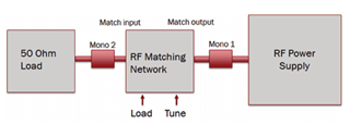
RF match box failure
The RF matching network usually consists of load and tune capacitors as well as an inductive coil. In the ideal world, the matching unit should not absorb any power. In practice, the coil has some resistance and there is power loss through ohmic heating. This reduces the matching network efficiency and may cause the coil to fail over time. High voltages across the capacitors (and high current flow through them) can also cause degradation over time. Continuous changes in the quality of the match components cause process drift and even worse, it can lead to a catastrophic failure event.
Impedans solutions for RF Generator/Matchbox Failure
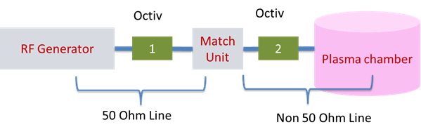
Impedans Octiv VI probes provide easy and quick solution to monitor the generator and match box heath. Place the Octiv on the output of the generator prior to any cabling. The Octiv can then be used to monitor the real power being output from the generator to test the generator’s health. Match box health can be monitored by checking if excess power is being lost across the matchbox. This is done by measuring the power going into the matchbox (Octiv directly before the match) and coming out of the match. To check if the match box has the correct impedance range for your process, or if your new matchbox has the same impedance range as your previous matchbox, the Octiv VI probe can be used to do Matchbox characterization.
Pressure Gauge Failures
Measurement Accuracy: Inaccurate pressure readings can lead to improper gas flow rates and plasma characteristics. Any malfunction can result in either too high or too low pressure, destabilizing the plasma.
Calibration Issues: A failure to regularly calibrate pressure gauges can lead to drift in measurements, causing inconsistent plasma behavior.
Gas Flow Controller Malfunctions
Flow Rate Variability: Fluctuations in the gas flow rate can significantly impact the plasma composition and stability. If the flow controller fails to maintain the desired setpoint, this can lead to rapid changes in plasma characteristics.
Contamination: Gas purity is critical; if the flow controller introduces contaminants due to failure, it can adversely affect plasma chemistry and performance.
Wafer Displacement Issues
Positioning Accuracy: Inaccurate wafer positioning can lead to uneven plasma exposure, resulting in non-uniform processing across the wafer.
Vibration and Mechanical Stability:External vibrations or mechanical instability in the wafer handling system can cause fluctuations in the plasma environment, leading to inconsistent results.
Thermal Effects: Changes in wafer temperature due to improper displacement can alter the plasma characteristics and the reactions occurring at the surface.
Impedans solutions for fault detection:
By installing Impedans Octiv VI probe on the RF line in Post match position, one can identify many faults on the tool through the access to the plasma impedance/plasma harmonic. Almost anything that changes inside the chamber will change the plasma impedance. The harmonics are often much more sensitive since they react non-linearly with changes in plasma impedance. In the 50 Ohm side, these harmonics are heavily attenuated by the match box and will have a poor signal to noise ratio. But one can see very strong changes in the harmonics compared to the fundamental using an Octiv VI probe in a post-match configuration as shown in figure 2.
Regular maintenance, calibration, and system checks can mitigate the risks associated with pressure gauge inaccuracies, gas flow controller malfunctions, and wafer displacement issues. By ensuring these components function reliably, one can achieve the desired stability and repeatability of plasma, ultimately leading to improved process outcomes.
Some other faults that have been observed using an Octiv Poly or Suite post-match are:
• Air/gas leaks
• Shower head issues
• Parasitic plasma formation
• Chamber conditioning/seasoning issues
Here is a procedure to characterize or identify fault signatures from your tool.
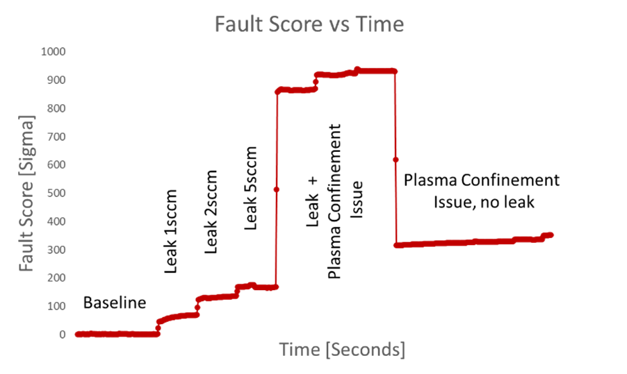
1. Collect baseline data. Run a recipe on the tool with a specific power/pressure, while ensuring to record all harmonics.
2. Deliberately introduce the faults you are looking to monitor within the tool. For example: add a few SCCM’s of nitrogen to simulate an air leak and observe how the harmonic spectrum changes. Some example data is shown in figure 3.
When a large amount of extra air was present, the plasma expanded out into the windows, hence the very large jump in the Fault Score. The extra plasma remained after the air leak was removed. This is detectable due to the change in the plasma impedance and in the plasma harmonic emissions.