Tool Maintenance and Repair
RF powered plasma enables the precise control required for etching and deposition processes in fabrication of microelectronic devices, ensuring high-quality and defect-free components. However, maintaining and repairing the RF generators, matching network and plasma tools are very crucial for ensuring high-quality production and minimizing downtime. Here are some common issues observed with these tools and their potential solutions. RF generators play a crucial role in plasma generation, but several key issues can impact their performance and, consequently, the quality of the plasma process. Here’s an overview of the main challenges:
Arcs
Arcing poses a significant challenge in high-voltage power supplies. While individual or intermittent arcing may not be critical, sustained arcing over time can lead to overheating of output limiters. In some instances, it has been found that generators can output power unexpectedly, even when the dial indicates zero—often due to a faulty relay switch. This malfunction can result in power surges lasting a few hundred microseconds, generating thousands of volts across the wafer. Such arcs not only disrupt production but can also result in expensive equipment damage and reduced yield.
Missed pulses
Pulsed RF generators occasionally fail to deliver signals at the required intervals, resulting in missed pulses. This can lead to inconsistent plasma generation, characterized by uneven ionization and reduced process uniformity, ultimately ausing instability in the overall process. Consequently, this can negatively impact the deposition rate and the quality of the produced film.
Power Drift
Power drift refers to unintentional fluctuations in the output power of the RF generator over time. This can occur due to temperature changes, component aging, or fluctuations in input voltage. This can result in inconsistent plasma density and energy distribution and eventually will lead to variability in process outcomes, impacting product consistency.
Harmonics
Harmonics are unwanted frequencies generated alongside the fundamental frequency of the RF signal. The main cause of the harmonic generation is the “non-linear” loads. Plasma being non-linear in nature produce multiple harmonics which can travel back to the generators and can be harmful.
Impedans solutions for maintenance and repair of RF generators:
Impedans offer a comprehensive suite of RF diagnostics such as Octiv VI probes and Alfven arc detector to address various challenges in the RF generators. Integrating Impedans VI probes will enable regular maintenance and real-time monitoring to mitigate these challenges effectively. These sensors offer easy integration into manufacturing platforms without increased cost or impact on process performance.


Alfevn RF event detector for arc detection and pulse monitoring:
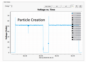
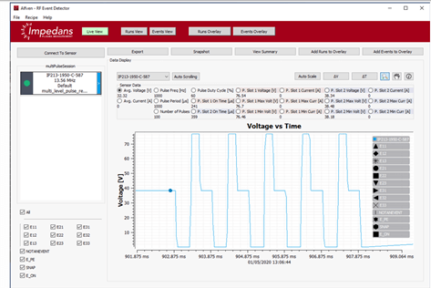
The Alfven radio-frequency (RF) event detector is designed to monitor short-lived, unexpected events in RF and plasma processes. It monitors events such as arcs, ignition phenomena, instabilities and pulsing with 1 μs resolution. Alfven is a single frequency sensor suitable for in-line monitoring of voltage, current and categorized event count (i.e. No. of arcs of particular duration and magnitude).
Alfven is designed to detect and characterize arcs while simultaneously monitoring every RF pulse to check that each pulse is within a predefined specification (pulse frequency, duty cycle, max, min, average pulse voltages and currents during the pulse-on time). Arcs and misfiring RF pulses can lead to wafer defects; therefore, the Alfven 100 is an essential tool for rapid troubleshooting and 24/7 monitoring.
Octiv VI probe for power and harmonic monitoring:
The Octiv V-I Probes are a range of compact sensors for measurements of various RF parameters such as power, voltage, current and impedance at typical RF process impedances. They are completely pulse-compatible and have a wide variety of communication options for easy use in the field.
Octiv Suite 2.0 V-I probe
Octiv Suite 2.0 V-I probe is a non-intrusive, in-line sensor used to monitor the RF harmonic spectrum and waveform at the RF process input in real time to enable process and/or equipment control. Uniquely convenient form-factors enable retrofitting to match box outputs to facilitate direct plasma monitoring as well as in pre match positions to monitor the RF generator health. Issues such as power drift in generators can be monitored easily by installing the Octiv at generator outputs. Installed in the post-match position, it can monitor plasma harmonics.
RF Match Units characterization
One of the critical components of a radio-frequency (RF) plasma processing equipment’s power delivery system is the RF matching unit. The RF matching network consists of load and tune capacitors as well as an inductive coil. In the ideal world, the matching unit should not absorb any power. In practice, the coil has some resistance and there is power loss through ohmic heating. This reduces the matching network efficiency and may cause the coil to fail over time. High voltages across the capacitors (and high current flow through them) can over time. Continuous changes in the quality of the match components cause process drift and even worse, it can lead to a catastrophic failure event. Matching unitcharacterization is now a key requirement for fab managers and process engineersthroughout the industry.
Impedans solutions for RF match unit characterization:
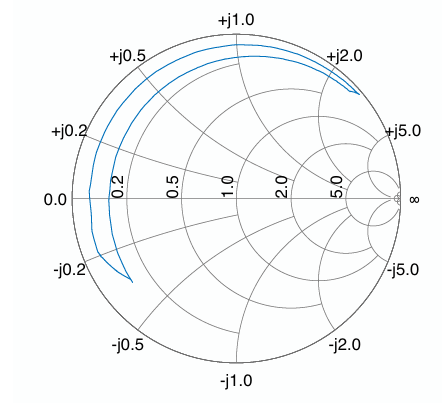
There are three key performance indicators for the matching network: the match impedance range, the match quality and the match efficiency including the internal resistance. The Octiv Mono VI probe and is the ideal product for characterizing the matching network in terms of these three parameters. Octiv Mono VI probe for checking the impedance range of match unit: The matching network impedance range determines the range of plasma process impedances for which theRF power can be fully matched. The smith chart in figure 5 shows the full range of a test matching network as measured by Octiv Mono VI probe. The plasma impedance range is simply the complex conjugate of the matching network impedance range.
Octiv Mono VI probe for checking the quality factor of match unit:
The quality factor Q of the matching network is one of the most important quantities that can be measured with Octiv mono VI probe.
Octiv Mono VI probe for checking the matching network efficiency:
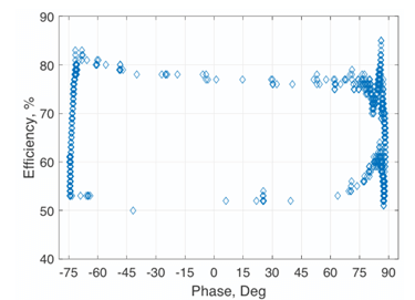
The impedance of the matching network components would ideally consist of reactance only in order to have no power dissipation within the matching network. However, real components are lossy and so will dissipate some power. The power efficiency of the matching unit is defined as the ratio of power measured at output to the input. Interestingly, at certain match positions the efficiency can be as low as 50%.
Plasma Tools:
Maintenance and repairing RF plasma tools is essential for ensuring optimal performance, reliability, and longevity in semiconductor manufacturing. Some common faults observed on plasma tools are wafer displacement issues, air/gas leaks, shower head issues, parasitic plasma formation and chamber conditioning/seasoning issues etc.
Impedans solutions for fault detection on plasma tools:
With access to the plasma impedance/plasma harmonic many faults can be identified on a plasma tool. To know a detailed procedure to characterize or identify fault signatures from your tool using Impedans Octiv VI probe please visit our section on fault detection.